This is an ideal “portable” aerial when you want the most bands from a single set of wires without having to worry about an ATU – plus it’s quite fun to make.
Essentially, it’s a 40m Inverted-V Dipole but with “breaks” in the wires at certain points with crocodile-clips soldered onto each piece of wire end. This allows the electrical length of the aerial to be changed – and quickly become resonant on 30m/20m/17m without having to change wires or move/adjust ground-pegs or support lines.
My post-it-note calculations are shown: 300/freq is the metric calculation to give you the wavelength, so 150/freq is the whole Dipole length and 75/freq is each individual wire. This is a proven formula for getting wire lengths in the ball-park of where you want them to be.
Note: When you change the angle of wires on a Dipole to form an Inverted-V, the resonant frequency drops – and you typically end up cutting the wire 5% shorter than were it in a flat-top configuration. You may find that the length of a 40m Inverted-V wire is just under 10-metres. You will probably find this out after a rinse’n’repeat session of what I call Prune&Tune!
The wire used was 2.5mm 24/0.2 which I get from CPC. and is available in a variety of gaudy colours.
A very useful aspect of an Inverted-V is that it only requires 1 vertical support so is ideal for portable operations. On a conventional Inverted-V, there’s nothing to stop you adding a 2nd pair of wires for another band – this not only gives you a dual-band HF aerial but also helps support the pole if the wind picks-up. An added bonus is that you can orientate the 40m wires so that the RF lobes are North/South (perfect for inter-G) and the 20m wires East/West – just right for working into EU or over to the United States. See my Portable page for an example of this type of arrangement.
It should be noted that, at ground-level, the Inverted-V is mostly omnidirectional, but it doesn’t hurt to get into the practice of knowing which direction the RF is going.
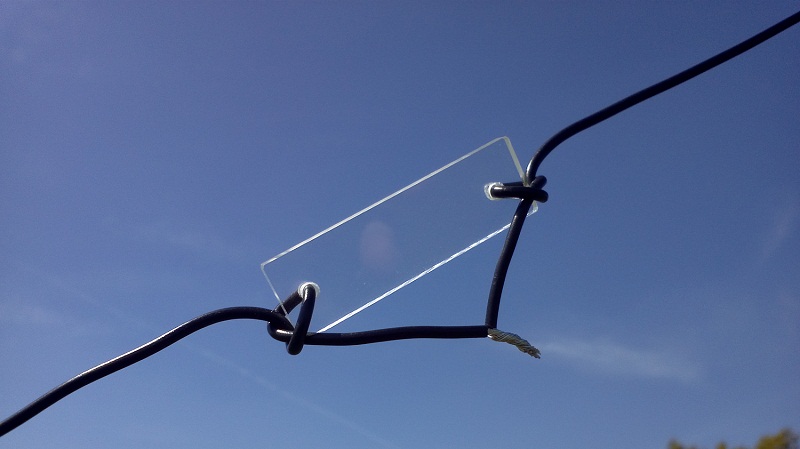
Each section of wire is separated by a piece of clear plastic 50mmx15mm. You don’t even have to go that far – a short piece of non-conductive cord would also be suitable. Here’s how a spacer looked during tests at the local park:
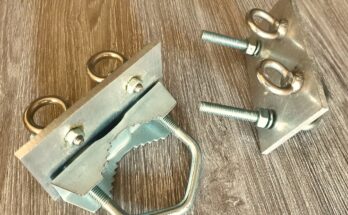
For a more permanent solution, a set of red crocodile-clips were soldered onto the ends and this makes it really easy to change bands. All that’s required is to lower the sections on my 10m telescopic fishing-pole until I can reach the clips, (un)clip them and raise the pole back up. You could also use “bullet” style connectors – anything that makes it easy to connect and separate the wires without the ends becoming frayed or weathered.

Down at the ground end, I made use of my existing “dog-bone” insulators and yellow nylon support-cord which are around 1m long. As it’s still a 40m Inverted-V Dipole, the geometry is no different so setting-up the whole lot is just a case of me raising the pole and walking 12 paces either side to place the ground-pegs.
For other pole heights (or different bands), your schoolboy/girl maths and Pythagoras of Samos will tell you how far apart the ground-pegs need to be if you know the height of the feed-point and the length of the wire – and you can reverse the equation if you want to how much wire you can fit into your garden.

Here’s how things looked on the MFJ-259 at the end of 12m of RG58 coax: 17m looking good:

20m just right:

30m – ready for some CW:

Things seem OK on 40m – although by adjusting the wire angle, this sweet-spot can be changed:

So with each section tuned for operation roughly in the centre of where I will be operating, it makes life easier as you don’t need to worry about using a tuner or carrying individual wires for each band… Just Clip ‘n’ Go!